Circuit diagram:
Parts:
P1______________47K  Log. Potentiometer
                     (twin concentric-spindle dual gang for stereo)

R1,R2,R4_______100K  1/4W Resistors
R3,R10_________560R  1/4W Resistors
R5_______________1K  1/4W Resistor
R6______________56K  1/4W Resistor
R7______________15K  1/4W Resistor
R8_____________220K  1/4W Resistor
R9______________22K  1/4W Resistor

C1_______________1µF  63V Polyester Capacitor
C2_____________100pF  63V Polystyrene or Ceramic Capacitor
C3______________22nF  63V Polyester Capacitor
C4______________12nF  63V Polyester Capacitor
C5_______________3n3  63V Polyester Capacitor
C6,C9__________100nF  63V Polyester Capacitors
C7,C10___________4µ7  25V Electrolytic Capacitors
C8,C11________2200µF  25V Electrolytic Capacitors

IC1___________TL072   Dual BIFET Op-Amp
IC2___________78L15   15V 100mA Positive Regulator IC
IC3___________79L15   15V 100mA Negative Regulator IC

D1,D2________1N4002  200V 1A Diodes

SW1____________DPDT  Toggle Switch
SW2____________DPST  Toggle Switch

J1,J2,J3,J5____RCA audio input sockets
J4_____________Mini DC Power Socket
Comments:
This module is the same of the well known and very successful Modular Preamplifier Control Center posted earlier to this website. It differs from its predecessor only for the Loudness Active Control instead of the passive one.
This feature allows the use of less gain in the amplification stage and a better signal to noise ratio, leaving all other features unchanged.
The circuit features a single loudness curve instead of two: it can be switched on and off by means of SW2.
For a complete description of the circuit and full specifications please refer to the Modular Preamplifier Control Center page.
Notes:
- The circuit diagram shows the Left channel only and the power supply.
- Some parts are in common to both channels and must not be doubled. These parts are: P1 (if a twin concentric-spindle dual gang potentiometer is used), IC2, IC3, C6, C7, C8, C9, C10, C11, D1, D2, SW1, SW2 and J4.
- This module requires an external 15 - 18V ac (50mA minimum) Power Supply Adapter.
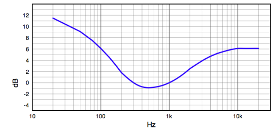
Loudness Frequency Response: