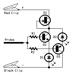
Circuit diagram:
Parts:
R1,R2___________22K  1/4W Resistors

D1______________LED  (Any dimension and shape, preferably red)
D2______________LED  (Any dimension and shape, preferably green)

Q1____________BF245 or 2N3819 General-purpose N-Channel FET
Q2____________BC547   45V 100mA NPN Transistor
Q3____________BC557   45V 100mA PNP Transistor

Probe_________Metal Probe 3 to 5 cm. long

Two Miniature Crocodile Clips (Red and Black)
Comments:
This little circuit indicates the basic integrity of a printed board, detecting 0V, positive supply voltage from less than 3V to 30V and floating parts.
If the probe is floating, as it would be in a broken track, then both LEDs barely light up, since there is no current to drive the transistors, but if the probe touches 0V or a positive voltage one or other lights. A digital signal should light them in proportion to the mark-space ratio whereas the output of a circuit oscillating at a frequency rate below about 20Hz will cause the LEDs to flicker alternatively.
The LEDs will illuminate always at a constant intensity, no matter the voltage supply used, because they are fed by a very simple Fet constant-current generator (Q1).
Note:
- The Black clip must be connected to the negative ground of the board under test.
The Red clip should be connected to a positive voltage source (not exceeding 30V) available on the same board.