Circuit diagram:
Parts:
R1_____________500K  1/2W Trimmer Cermet or Carbon
R2______________47K  1/4W Resistor
R3,R5,R7,R9______4K7 1/4W Resistors
R4,R6,R8,R10___470R  1/4W Resistors

C1_______________1µF  63V Polyester or electrolytic capacitor
C2_____________220µF  25V Electrolytic capacitor

D1-D4__________LEDs Yellow ultra-bright types

Q1,Q2,Q3,Q4___BC337   45V 800mA NPN Transistors

IC1____________7555 or TS555CN or TLC555CP CMos Timer IC
IC2____________4017 Decade counter with 10 decoded outputs IC
IC3,IC4________4013 Dual D-Type Flip-Flop

SW1____________SPST Switch, any type suitable to the vehicle

Battery_________12V Vehicle battery
Comments:
This circuit was designed on request: the correspondent wanted an easy and quickly to build Four-LED bar that, unlike the majority of these devices, must operate in bar mode, i.e. the four LEDs should light in sequence but should remain lit until the fourth LED was reached. Then the sequence restarts.
For simplicity, the use of special ICs was avoided and four easy to locate chips were arranged to perform the bar sequence.
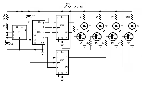
The 7555 CMos timer (IC1) is wired as an astable multivibrator driving a Decade counter (IC2). This IC is set to count a sequence of four by connection of pin #10 to pin #15 and the four outputs drive the Set pin of as many D-type Flip-Flops contained in IC3 and IC4. These Flip-Flops are reset after the four-count cycle together with IC2.
The LEDs are driven by four BC337 transistors, able to sustain an output current of about 300mA each. If higher currents are required, Darlington types like BD177, BD179, BD181 should be used without further modifications.
Notes:
- For the best performance use high brightness, high efficiency LED types of suitable size.