Parts:
P1_____________50K  Lin. Potentiometer (or 47K)
P2_____________50K  Log. Potentiometer (or 47K)

R1______________1K  1/4W Resistor
R2,R3_________180K  1/4W Resistors
R4,R5,R6________1M  1/4W Resistors
R7____________100K  1/2W Trimmer, Cermet or Carbon
R8____________220R  1/4W Resistor
R9____________220K  1/4W Resistor
R10_____________4K7 1/4W Resistor
R11____________10R  1/4W Resistor
R12_____________1R  1/4W Resistor
R13_____________2K2 1/2W Resistor
R14____________10K  1/2W Trimmer, Cermet or Carbon (Optional)

C1_____________10nF  63V Polyester Capacitor
C2_____________22nF  63V Polyester Capacitor
C3,C5_________220nF  63V Polyester Capacitors
C4______________1µF  63V Polyester Capacitor
C6_____________47µF  25V Electrolytic Capacitor
C7____________470µF  25V Electrolytic Capacitor
C8___________1000µF  25V Electrolytic Capacitor
C9_____________22µF  25V Electrolytic Capacitor (Optional)
C10__________2200µF  25V Electrolytic Capacitor

D1___________1N4148  75V 150mA Diode (Optional)
D2______________LED  (Any color and size) See Notes
D3,D4________1N4004 400V 1A Diodes

Q1,Q2_______2N3819   or BF245 General-purpose N-Channel FETs
Q3___________BC337   45V 800mA NPN Transistor
Q4,Q5_______P25N06   60V 25A N-Channel Hexfet Transistors
                      or P25NE06 or P25N05
                      or IRF530  100V 14A N-Channel Hexfet Transistors

IC1___________7824   24V 1A Positive voltage regulator IC

J1__________6.3mm. Mono Jack socket

SW1___________SPST Mains switch

T1____________220V Primary, 48V Center-tapped Secondary
                     20VA Mains transformer

PL1___________Male Mains plug with cord

SPKR__________One or more speakers wired in series or in parallel
                     Total resulting impedance: 8 Ohm
M1____________Milliamp meter 0-1mA dc fsd (Optional)
Comments:
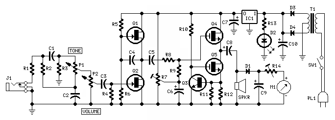
This small Guitar Amplifier was designed to provide every DIY enthusiast with a circuit that could mimic most of the so-called "Pawn Shop Amplifiers" available on the market.
Usually, those tube amps are able to deliver a few watts of output power, claiming also a particular, "vintage" sound. The Clara Guitar Amp is able to provide a clear sound as its name, using FETs and MOSFETs throughout and will deliver more than 2W in pure Class-A.
The output stage is formed by MosFet Q4 wired in a single-ended, Source-follower configuration with active load (Q5 & Q3)
As such a stage has an ac gain which is a bit less than unity, it must be driven by a preamplifier stage capable of delivering the full output voltage swing, i.e. about 11.5V peak-to-peak for 2W RMS into an 8 Ohm load.
This task can be easily accomplished by a two-FET Cascode stage similar to that employed in the highly successful Solid-state Fender Blackface Preamp available on this web site.
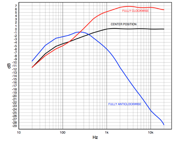
The preamp stage is preceded by the Volume Control and a single-knob Tone Control similar to those found in vintage guitar amps (see frequency curves in the figure below).
Tone Control Frequency Response:
Some amplifiers on the market feature also a cool visual element, i.e. the backlit, test-instrument-like needle readout, which provides a visual indication of where you are in the clean-to-overdriven range of the amp.
Unfortunately, needle micro or milliamp meters are exceedingly costly and the implementing of such a simple facility can be prohibitive.
I had therefore decided not to add this facility, until I have found on eBay several suitable instruments at a price as low as about $5. At this cost, the clean-to-overdriven range indicator is worth to be added.
Heatsinks
The only snag of this simple circuit is that the two MosFets generate a large amount of heat. In fact, they dissipate about 8W each and, therefore, rather large heatsinks should be used. A finned, blackened heatsink of about 80x40x25mm (minimum) for each mosfet will do the job.
The regulated power supply circuit is straightforward and employs a 7824, 3-Terminal 24V Regulator IC. This device will dissipate about 2W (provided the voltage across C10 is around 27V, as expected if a 24V 20VA transformer is used for T1), i.e. much less than the output MosFets. Therefore, a similar, but smaller heatsink must be fitted to IC1.
Amplifier setup
After applying power to the circuit, adjust Trimmer R7 in order to read 12V on a dc voltmeter connected across the positive lead of C8 and negative ground.
Power indicator setup
The power indicator should be set when the amplifier is delivering 1W into 8 Ohms load with a 1kHz sine wave input.Connect an oscilloscope or an ac voltmeter across the loudspeaker and connect the output of a 1kHz sine wave oscillator to the input of the amplifier.
Adjust the volume control P2 to read 8V peak-to-peak on the oscilloscope or 2.8V RMS on the ac voltmeter. Adjust R14 unless the reading of M1 is exactly 0.6 (mA).
As the scale of these indicators shows usually markings at 0.2, 0.4, 0.6, 0.8 and 1 (mA), the corresponding power values are 0.25, 0.56, 1, 1.5 and 2.25 Watts respectively.
Notes:
- Total current drawing of the amplifier is about 650mA and should not require adjustment. This is set by the resistance value obtained by paralleling R11 and R12, i.e. 0.9 Ohm.
- Some needle readout instruments on the market embed a LED. If the case, you can use it in place of D2.
Technical data:
- Output power:
- 2W RMS into 8 Ohms (1KHz sine wave)
- Input sensitivity:
- 140mV RMS for full output
- Frequency response @ 1W RMS:
- See frequency curves in the above figure
- Total Harmonic Distortion @ 1KHz and 10KHz:
- 0.5W 0.5% 1W 1.5% 2W 3.5% 2.6W 6.5% 3W 35%